ELECTROSTATIC PENDULUM EXPERIMENT
WHICH PUMPS ENERGY FROM THE ETHER
By Cornille Patrick ( France )
Created on 11/07/97 - Last update 03/09/99
The violation of Newton's third principle implies consequences that can be tested experimentally, namely a charged capacitor at rest in the Earth reference frame can set itself in motion and accelerate its center of mass without external help.
1. Newton's third principle in NEWTONIAN mechanics
It is fundamental to recall some basic definitions in classical mechanics (1-5). Newton's second law of motion states that the motion of two particles in a given reference frame is described by the differential equations:
(1)
with the following definitions P1 = m1U1 and P2 = m2U2. We must distinguish between the internal forces F12 and F21 and the external forces F11 and F22 acting on the particles due to sources outside the system. We can speak of mutual interaction between two particles only if the internal forces follow Newton's third principle, namely F12 = -F21. Therefore, an external force is by definition a force that does not follow Newton's third principle. When the external forces are zero, we say that the system is closed or isolated.
The center of mass of the system is a fictitious point r where the entire mass m = m1 + m2 of the system can be thought to be concentrated. It is defined by:
mr = m1r1 + m2r2 (2)
The motion of this point is only determined by the effect of external forces since we have:
We can now study the motion of a second fictitious particle called the relative particle with a reduced mass M = m1m2/(m1 + m2). This single particle is located at the place occupied by either the first or the second particle depending on our choice of the rest position as shown in Fig.1. The distance R is therefore R12 = r1 - r2 if particle 2 is located at the origin of a reference frame or R21 = r2 - r1 if particle 1 is now the origin of our reference frame. For each choice, we have an equation of motion:
(4)
where the relative velocity V = dR/dt between the two reference frames is reciprocal since we have V12 = -V21. It follows that the reciprocity V12 = -V21 of the rest reference frame is linked to the existence of Newton's third principle as shown in Fig.1 for the three possibilities. The reciprocity concept and the Newton's third principle are two faces of the same coin. Therefore, we cannot use the reciprocity of the reference frames in special relativity and at the same time state that Newton's third principle does not apply in special relativity.
2. Conservation of energy and over-unity devices
By definition, the equation of conservation of energy must be satisfied:
When the external forces are zero F11 = F22 = 0, the system is closed or isolated, in that case, we get:
It follows that
the velocity U = dr/dt and the kinetic energy ![]() of the center of mass
are constant. Thus, Newton's third law can be interpreted as a
law of momentum exchange. Hence a failure of the third law would
be a failure of momentum conservation. The law of momentum
conservation is regarded by physicists as more fundamental than
Newton's law because it holds in quantum mechanics as well as in
classical mechanics with no known exception.
of the center of mass
are constant. Thus, Newton's third law can be interpreted as a
law of momentum exchange. Hence a failure of the third law would
be a failure of momentum conservation. The law of momentum
conservation is regarded by physicists as more fundamental than
Newton's law because it holds in quantum mechanics as well as in
classical mechanics with no known exception.
If the external forces are zero and the internal force F12 is derivable from a potential function EP(R), the equation of motion for the reduced mass becomes:
One can multiply the two sides of the above equation by V to obtain:
Therefore, we have conservation of mechanical energy only in the case where the internal forces are central and satisfy Newton's third principle for translation. As an example, let us consider the case of a simple non-relativistic harmonic oscillator of mass m1 and spring constant k0 fixed to a wall of mass m2 > m1. The equation of motion for the displacement of the mass is:
where the
internal force derives from a potential ![]() Since k0 is constant, the
potential does not depend explicitly on time, therefore the
system is closed and the mechanical or total energy ET is also
constant:
Since k0 is constant, the
potential does not depend explicitly on time, therefore the
system is closed and the mechanical or total energy ET is also
constant:
Since the splitting between internal and external forces is independent of the origin of the force, this partition must apply in all branches of physics, namely: classical physics, special relativity, electromagnetism and quantum mechanics. Therefore, special relativity and quantum mechanics are both incomplete theories, since they imply the existence of internal forces associated to the reciprocity concept and the conservation of energy and ignore the existence of external forces. We must point out that the Lorentz force cannot be considered as an internal force because this force violates Newton's third law. The existence of external forces which do not satisfy Newton's third law deserves special attention since one must recognize from the above calculation that there is no energy conservation principle for that kind of force. Since the Lorentz force does not follow Newton's third principle, this force can be used for building the so-called free-energy devices.
2.1. Calculation of the stimulated force for a charged capacitor
The violation of Newton's third principle by the Lorentz forces implies that a charged capacitor must accelerate its center of mass without external help if the capacitor has an absolute motion with respect to the ether. Moreover the existence of an external force must also result in the violation of energy conservation.
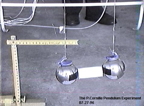
The experiment showing the linear stimulated motion of the capacitor through the ether has already been reported elsewhere (3,4,6). The experiment as shown in Fig.2 consists of two heavy metallic balls suspended by fine cotton wires to the ceiling of the laboratory. In order to keep the balls at a fixed distance D, an insulating rod is used between the balls. Therefore, the bi-filar pendulum with the two balls make a capacitor that moves as a solid with the Earth's velocity U = Ui where Ui is also the ionic velocity defined with respect to the ether frame.
We know that an electric current circulating through a metal consists in the motion of free electrons contained in the body of the metal. If the capacitor moves through the ether, the free electrons will be accelerated differently, lagging behind with a relative drift velocity V = Ui - Ue. This effect has been shown to exist in the Earth frame by Tolmann and Barnett (7,8) and must also exist in the ether frame since V is the same quantity in any frame. At all times, there is an electron drift motion in each plate trying to follow the motion of the ions in the two plates. Therefore, the stimulated force will exist if there is always a drift velocity between the electrons and the ions. This drift velocity can be increased if the capacitor is not perfect, in that case, there is a leakage current which will enhance the magnitude of the stimulated force.
In a first step, let us assume that only the presence of electrons and ions on the surface of the balls and the wires affect the calculation, this implies that all the internal forces cancel one another. In that case, the stimulated force is then proportional to the square of the applied voltage V0 by virtue of the formula Q = CV0 where C is the capacity of the capacitor, therefore, we get (2):
where D can be
taken as the distance between the center of the two balls. If d =
6.7 cm is the diameter of a ball, the capacitance can be
calculated from the formula ![]() ,
knowing that D = 2d, we get C = 15d/48 =
2.09 cm or 2.33 pF. The capacitance of the bi-filar line which
brings the voltage to the balls is given by the formula
,
knowing that D = 2d, we get C = 15d/48 =
2.09 cm or 2.33 pF. The capacitance of the bi-filar line which
brings the voltage to the balls is given by the formula ![]() where d = 0.05 cm is
the diameter of the wires and D = 14 cm is the distance between
the two wires. Therefore, we get C = 8.8 pF for a line of length
L = 2 m. The relative drift velocity of the free electrons
circulating in the wires and the balls is small, about V = 10-1
cm/s. Knowing that
where d = 0.05 cm is
the diameter of the wires and D = 14 cm is the distance between
the two wires. Therefore, we get C = 8.8 pF for a line of length
L = 2 m. The relative drift velocity of the free electrons
circulating in the wires and the balls is small, about V = 10-1
cm/s. Knowing that ![]() and
and ![]() or 50 kV, we get a
small force
or 50 kV, we get a
small force ![]() for
for ![]() surface
electrons. The formula 11 gives the minimum force one can expect
from a calculation that neglects volume forces. The value of the
stimulated force will be greatly enhanced if the charges inside
the balls participate to the calculation of this force and if the
total resulting force does not cancel. The number of conducting
electrons in a body of mass M is given by the formula Ne =
neM/(mpA) where ne is the number of free electrons per atom.
Therefore, we realize the importance of the quantity Q = Neq
since the stimulated force is roughly proportional either to
surface
electrons. The formula 11 gives the minimum force one can expect
from a calculation that neglects volume forces. The value of the
stimulated force will be greatly enhanced if the charges inside
the balls participate to the calculation of this force and if the
total resulting force does not cancel. The number of conducting
electrons in a body of mass M is given by the formula Ne =
neM/(mpA) where ne is the number of free electrons per atom.
Therefore, we realize the importance of the quantity Q = Neq
since the stimulated force is roughly proportional either to ![]() . This effect has been
tested in the experiment described below.
. This effect has been
tested in the experiment described below.
The direction of the stimulated force and the resultant motion thereby produced are toward the positive electrode of the capacitor as shown by the experiment described hereafter. The formula 11 shows that it is the magnitude and not the direction of the stimulated force that will vary with the direction of Earth's absolute motion through the ether. To show this effect, one must register the amplitude of this force during months which is not possible at the present time. However, we tested the direction effect by switching the poles of the generator in the experiment. We verify that the direction of the stimulated force has indeed changed 180° since this force depends on the direction of the current given by V in Eq. 11.
2.2. The pendulum experiment
The figure 2
shows a pendulum of mass nM where M is the mass of one ball, n
the number of balls and L is the length of the string which makes
an angle ![]() with the
vertical. The forces acting on the system are the gravitational
force nMg, the tension T in the string and the
stimulated force FG. The horizontal component of the
tension force is balanced by the stimulated force FG when the
stationary state is reached, therefore we have
with the
vertical. The forces acting on the system are the gravitational
force nMg, the tension T in the string and the
stimulated force FG. The horizontal component of the
tension force is balanced by the stimulated force FG when the
stationary state is reached, therefore we have ![]() where
where ![]() is the displacement of
the ball.
is the displacement of
the ball.
The bi-filar
pendulum was placed in the middle of the laboratory room empty of
any metallic object. We used high quality power supplies which
were grounded and lied on a table which is parallel to the axis
of symmetry of the capacitor. The distances between the
laboratory walls and the balls or the wires are about h = 2.25 m.
The wall surface is about ![]() ,
therefore the induced force (9,p.122) between one ball and the
insulating wall of the laboratory room is less than
,
therefore the induced force (9,p.122) between one ball and the
insulating wall of the laboratory room is less than ![]() which is
which is ![]() smaller than the force
smaller than the force ![]() between one wire and
the wall, knowing that
between one wire and
the wall, knowing that ![]() is the capacity of the wire with respect to the wall. Any
perturbation of the symmetry of the laboratory geometry will
induce a force which will be smaller than
is the capacity of the wire with respect to the wall. Any
perturbation of the symmetry of the laboratory geometry will
induce a force which will be smaller than ![]() . Moreover, we did test this effect by
switching the polarity of the power supplies with no observable
effect on the magnitude of the stimulated force except that the
direction of the force changes 180°.
. Moreover, we did test this effect by
switching the polarity of the power supplies with no observable
effect on the magnitude of the stimulated force except that the
direction of the force changes 180°.
The leakage current I = 1,5 ma is mainly due to the thin nude wires d = 0.5 mm which induce the ionization of the air surrounding the wires and the balls. Since the stimulated force is proportional to the current I = Nq|V|S where S is the cross section surface of the metallic conductors, we can test the induced forces in the surrounding environment by replacing the nude wires by coated wires. In that case, the leakage current drops to 0.003 mA and no translation motion of the pendulum was observed in spite of the fact that the electrostatic forces are rigorously the same in both cases. We can conclude that no induced forces in the surrounding environment can explain the existence of the huge stimulated force. As soon as the voltage is increased, one can see a thrust of the two balls in the direction of the positive ball.
The original P.Cornille Experiment (07-27-96)
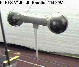
The JL Naudin's testing (09-11-97) Click
on the picture above for more details
One may think
that the corona effect and ionization in the air surrounding the
wires can explain the existence of the stimulated force. But the
corona discharges around each thin cylindrical wire must have the
same cylindrical symmetry and therefore no reaction effect can be
expected from the corona discharges. However, let us assume that
the motion is due to a direct collision of both positive and
negative ions with the metallic conductors. Then the transfer of
momentum must be attributed to the difference of masses between
the two kinds of ion, namely the masses of the emitted electrons.
In A. D. Moore's book (10,p84), it is stated that ![]() electrons per second
leave the negative electrode for a corona amounting to
electrons per second
leave the negative electrode for a corona amounting to ![]() . For a 1.5 mA leakage
current, we obtain
. For a 1.5 mA leakage
current, we obtain ![]() which
amounts to a mass transfer
which
amounts to a mass transfer ![]() which is several orders smaller than the 3.5 g stimulated force
observed. Moreover, as shown in Fig. 4, the stimulated force is
roughly proportional to the mass, this fact cannot be explained
by an ionization effect since both the voltage and the leakage
current are the same for different values of the mass. Therefore,
the thrust observed cannot be caused by ambient ion momentum
transfer when the experiment is conducted in the air. Moreover,
Deyo's experiments (11) at low voltage and high current shows the
same stimulated force with no possible ionization effect. Due to
the leakage current, the capacitor (wires + balls) can be
considered as a linear conductor of length L = 2 m located in the
Earth's magnetic field. In that case, there is a force applied to
the conductor given by the relation
which is several orders smaller than the 3.5 g stimulated force
observed. Moreover, as shown in Fig. 4, the stimulated force is
roughly proportional to the mass, this fact cannot be explained
by an ionization effect since both the voltage and the leakage
current are the same for different values of the mass. Therefore,
the thrust observed cannot be caused by ambient ion momentum
transfer when the experiment is conducted in the air. Moreover,
Deyo's experiments (11) at low voltage and high current shows the
same stimulated force with no possible ionization effect. Due to
the leakage current, the capacitor (wires + balls) can be
considered as a linear conductor of length L = 2 m located in the
Earth's magnetic field. In that case, there is a force applied to
the conductor given by the relation ![]() . Knowing that the Earth's magnetic field
is about B = 0.5 gauss, the magnitude of this force is
. Knowing that the Earth's magnetic field
is about B = 0.5 gauss, the magnitude of this force is ![]() . Therefore, the thrust
observed cannot result from the Earth's magnetic field since the
Laplace force due to the leakage current is smaller than the
stimulated force by several orders of magnitude.
. Therefore, the thrust
observed cannot result from the Earth's magnetic field since the
Laplace force due to the leakage current is smaller than the
stimulated force by several orders of magnitude.
The animated picture above shows the strength of the stimulated force
To measure the
displacement x of the pendulum when it reaches the stationary
position, we used two wood plates placed near each ball at the
same distance which is measured before the balls are charged.
This distance is measured when the positive ball almost touches
the positive wood plate. We also used the wood plates to test the
space-charge effects in the surrounding environment since these
effects are greater than the corresponding effects induced by the
laboratory walls. We know that an insulating plate always exerts
less influence than a conducting plate. Knowing the charge ![]() statcoulomb, we can
estimate that the force exerted by the wood plate on a ball will
be less than
statcoulomb, we can
estimate that the force exerted by the wood plate on a ball will
be less than ![]()
![]() is the surface of the
wood plate. The magnitude of this force must be compared with the
magnitude of the stimulated force which is about
is the surface of the
wood plate. The magnitude of this force must be compared with the
magnitude of the stimulated force which is about ![]() for two balls charged
at 50 kV. To test the fact that the force exerted by a wood plate
on a ball is smaller than the stimulated force, we put only one
wood plate near by the negative ball. When the voltage is
increased, one can see the pendulum attracted by the wood plate,
at about 30 kV when the stimulated force takes over, one can see
the pendulum moving away from the wood plate in the direction of
the positive ball. However, when we used two wood plates, the
forces of attraction on the two balls cancel one another since
the insulating plates attract the balls in opposite direction.
Therefore the induced force due to a lack of symmetry in the wood
plates is quite small.
for two balls charged
at 50 kV. To test the fact that the force exerted by a wood plate
on a ball is smaller than the stimulated force, we put only one
wood plate near by the negative ball. When the voltage is
increased, one can see the pendulum attracted by the wood plate,
at about 30 kV when the stimulated force takes over, one can see
the pendulum moving away from the wood plate in the direction of
the positive ball. However, when we used two wood plates, the
forces of attraction on the two balls cancel one another since
the insulating plates attract the balls in opposite direction.
Therefore the induced force due to a lack of symmetry in the wood
plates is quite small.
The distances x measured for two balls weighting M = 500 g are respectively 3,5,8 mm for the applied voltage 30,40,50 kV and 8,5,5 mm for n balls 2,4,6 charged with a potential 50 kV. These distances are used to plot the magnitude of the stimulated force as a function of the voltage in Fig.3 and of the mass in Fig.4.
The accuracy of
the measurements is roughly ±1 mm. The experiment is perfectly
reproducible and we did it several times for many physicists who
witnessed the experiment. Since the ![]() dependence of Eq. 11,
the stimulated force is too small to be measured with a good
accuracy below 30 kV. However, the accuracy with two different
kinds of measurement is largely sufficient to prove the existence
of the effect which is of course the main point of this
experiment. The results are reliable since we can increase the
effect to 5 cm by oscillating the high voltage. In that case, no
measurement is indeed necessary to prove the existence of this
effect. We also used another method to measure the displacement
of the balls which consists to place a measuring wood rod
parallel to the pendulum and takes a video movie of the
experiment when the voltage is switch on and off. By measuring
the amplitude of the oscillation one can determine the
displacement. We did check that the displacement measured with
the wood plates was almost the same as the displacement obtained
from the video recorder without the wood plates.
dependence of Eq. 11,
the stimulated force is too small to be measured with a good
accuracy below 30 kV. However, the accuracy with two different
kinds of measurement is largely sufficient to prove the existence
of the effect which is of course the main point of this
experiment. The results are reliable since we can increase the
effect to 5 cm by oscillating the high voltage. In that case, no
measurement is indeed necessary to prove the existence of this
effect. We also used another method to measure the displacement
of the balls which consists to place a measuring wood rod
parallel to the pendulum and takes a video movie of the
experiment when the voltage is switch on and off. By measuring
the amplitude of the oscillation one can determine the
displacement. We did check that the displacement measured with
the wood plates was almost the same as the displacement obtained
from the video recorder without the wood plates.
In classical circuit theory, the generator, the wires and the capacitor form a closed system where the conservation law of energy for internal forces applies. Therefore, the energy ES of the generator is converted into energy stored EP in the charged capacitor and into heat ER dissipated during the charging process, it follows the conservation law:
If the capacitor is not perfect, there is a leaking current and a corresponding dissipated energy which is provided by the generator. However, the above law will be violated when there is a stimulated force FG since we have now:
where FT
is the sum of the gravitational force nMg, the tension T
in the string and the stimulated force FG,
knowing that U is the velocity of the pendulum in the
Earth's reference frame. When the generator is switched off, a
kinetic energy ![]() is
recovered. This energy cannot be given by the generator but is
taken from the ether. For two balls charged at 50 kV, the kinetic
energy of the pendulum is
is
recovered. This energy cannot be given by the generator but is
taken from the ether. For two balls charged at 50 kV, the kinetic
energy of the pendulum is ![]() while the electrostatic potential energy is
while the electrostatic potential energy is ![]() . The kinetic energy due
to the stimulated force is not a small quantity and cannot be
taken from the generator since in classical circuit theory no
motion of the capacitor is taken into account during the charging
process. We also applied the high voltage in an oscillatory
manner in synchronism with the oscillatory motion of the
pendulum. It results in an amplification of the displacement of
the pendulum which reaches a magnitude of ± 5 cm. This implies the existence
of the stimulated force and an increase of the kinetic energy
almost 25 times the above kinetic energy.
. The kinetic energy due
to the stimulated force is not a small quantity and cannot be
taken from the generator since in classical circuit theory no
motion of the capacitor is taken into account during the charging
process. We also applied the high voltage in an oscillatory
manner in synchronism with the oscillatory motion of the
pendulum. It results in an amplification of the displacement of
the pendulum which reaches a magnitude of ± 5 cm. This implies the existence
of the stimulated force and an increase of the kinetic energy
almost 25 times the above kinetic energy.
2.3. Stan Deyo's and Michel Rambaut's experiments
Deyo points out in his book (11,p.171) that when an arc has been struck between a welding machine typically using 20-100 amperes of direct-current electricity at 20-60 volts and the aluminum stock, one notices the sudden jerking motion of the power supply wires connecting the hand-piece to the transformer. This phenomena can be explained either by using the Ampère force, in that case another part of the equipment must also move in opposite direction to counterbalance the momentum of the wires, or by the generation of a stimulated force applied to the center of mass of the equipment.
Deyo duplicates this phenomena by hanging a loop of 0.08 mm diameter wire across the laboratory room, each end of a portion of the wire was fixed to the walls. A car battery was used to supply the high-current to the test wire. When the power was applied to this experimental setting, the portion of the wire which drooped between the two anchor posts deflected toward one wall for a given polarity and toward the other wall when the polarity of the battery is reversed. In either case, as the circuit was closed, the wire deflection was momentarily exaggerated before coming to rest slightly off its unenergized position.
Deyo also tested the interaction of the Earth's magnetic field with the magnetic field of the wire by hanging four loops from the ceiling, each loop faced a direction of the compass. Whenever, he applied power to the system, the loops would all deflect equally either toward or away from the center of the loop arrangement as shown in Fig.5.
We know that two extended parallel conductors in close proximity mutually repel one another when carrying current in opposite directions. Although the portions of the wire which face one another are not in close proximity, the outside deflections can be easily explained by the action of the mutual repulsive Ampère's forces. However, the inside deflections corresponding to a change of the polarity of the battery contradict this interpretation since the currents are always circulating in opposite directions for the portions of the wire facing one another whatever the polarity of the battery.
Finally, Deyo repeated the first experiment with this time a portion of the wire which is tightly stretched between the anchor posts. Along the length of the portion of the wire were glued small strips of paper. All of them were in an upright position along the wire. When the power was applied to this configuration, the pieces of paper were seen to twist about the length of the wire and then to return to their upright, rest position after power was removed.
Deyo's experiments confirm the findings of the pendulum experiments described above. The nude wires in the pendulum experiments are fixed on the nylon wires supporting the two metallic balls. When we unloose the copper wires from the nylon wires, we can see an interesting phenomena, namely the oscillation of both wires bringing the high voltage to the balls. This oscillation can be explained as follows: the attractive electrostatic forces between the two wires bring then closer to one another and therefore increase the ionization current to a value where the repulsive magnetostatic forces take over. It then follows that the two wires move in the opposite direction from one another until the ionization current decreases to such a value that the electrostatic forces take over again and the whole cycle repeats again. However, one can see that the oscillations of the two wires are not symmetric since the magnitude of the oscillation of the positive wire is far greater and is subject to a torque which was so violent at one time that the wire unlooses it-self from the ceiling.
Dr. M. Rambaut is a retired scientist from the French Atomic Energy Commission who published several papers on the Ampère force and the cold fusion problem (12-17). He participated to the pendulum experiments described above. After witnessing the translation motion of the electrostatic bi-filar pendulum, not knowing Deyo's experiments, Dr. Rambaut duplicated these experiments in a different manner since he used a one ball pendulum connected to a low voltage generator (12 V) with a high current (4 A) crossing the metallic ball.
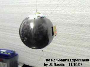
The JL Naudin's testing (11-19-97) Click on the picture above for more details
The experiment is so simple that any reader can repeat it in his garage and convince himself of the veracity of our assertion concerning the existence of the stimulated force. It suffices to connect a car battery with wires to the metallic ball. One must use very thin wires in order to provide the necessary resistance to avoid short-circuit the battery. Moreover, the fineness and the flexibility of the wires which must be hung from the ceiling prevent any mechanical coupling through an heating process between the wires and the ball (m = 0.5 Kg). As soon as the current is turn on, one can see, if the experiment is properly done, a rotation and a small translation of the ball. These effects can certainly not result from any wind effect or induction effects. To increase the translation effect, one can oscillate the D. C. voltage in phase with the oscillatory motion of the pendulum. The fact that the amplitude of the oscillatory motion increases is a proof that the stimulated force is an external force whose work increases the kinetic energy of the pendulum as anybody who has played with a swing in his youth knows very well.
see also : The Michel Rambaut's spinning ball - Design, pictures and tests by JL Naudin
References
1) P. Cornille, Derivation of the ether from anomalies in
Newton's third law, p. 103, New Frontiers in Physics, Vol I (Eds.
T. L. Gill), Hadronic Press, Palm Harbor, FL 34682-1577, U. S.
A., 1996
2) P. Cornille, The Lorentz force and Newton's third principle,
Can. J. Physics, Vol. 73, N° 9 &10, p. 619, (1995)
3) P. Cornille, Why Newton's third principle is the most
important principle in physics, International Conference:
Descartes and Scientific Thought 1596-1996 (Eds. U. Bartocci),
Perugia, 1996
4) P. Cornille, Newton's third principle in Physics, Physics as a
Science Hadronics Press, Inc., Palm Harbor, 1997
5) P. Cornille, Newton's third principle in post-Newtonian
physics-part I: Theory, Galilean Electrodyn., to appear (1999)
6) P. Cornille, Newton's third principle in post-Newtonian
physics-part II: Interpretation and Experiment, Galilean
Electrodyn., to appear (1999)
7) R. C. Tolman and T. D. Stewart, The electromotive force
produced by the acceleration of metals, Phys. Review, Vol. 8, N°
2, p. 97, (1916)
8) S. J. Barnett, A new electron-inertia effect and the
determination of m/e for the free electron in copper, Phil.
Magazine, Vol. 12, p. 349, (1931)
9) R. Becker, Electromagnetic Fields and Interactions, Dover
Publications, Inc., New York, (1964)
10) A. D. Moore, Electrostatics, Doubleday & company, Gaden
city, New York, New York, (1968)
11) S. Deyo, The Vindicator Scrolls, 1, West Australian Texas
Trading, P. O. box 71, Kalamunda, Western Australia, Australia
6076, Perth, (1989)
12) M. Rambaut, Phys. Letters A, Vol. 164, 13 April, p. 155,
(1992)
13) M. Rambaut, Phys. Letters A, Vol. 163, 30 March, p. 335,
(1992)
14) M. Rambaut, Frontiers of cold fusion, p. 601, ICCF3 , Nagoya,
21-25 October, Universal Academic Press, Inc., 1993
15) M. Rambaut, p. 24, ICCF4 , EPRI, July, 1994
16) M. Rambaut, Transaction of Fusion Technology, Vol. 26, N°
4T, p. 486, (1994)
17) M. Rambaut, p. 623, ICCF5 , Monte-Carlo, Monaco, 1995
The Electrostatic Pendulum Experiment - Questions and Answers
 The Cornille's Electrostatic pendulum Demystified ( April
13, 2002 )
The Cornille's Electrostatic pendulum Demystified ( April
13, 2002 )
Back to the Electrostatic Pendulum home page