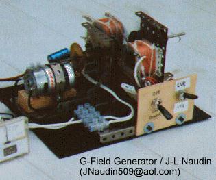
G-Field Generator (2.5 Watt R.Cole Generator)
J-L Naudin - Version 1.1 - Test date : 30 August 1996

This is G-Field generator based on "2.5 Watt R.Cole generator plan's" :
You can find this original G-field generator plan in Bedini lab's note at : http://rand.nidlink.com/~john1/motor.html
I have used :
- Two coils made with 450 turns of 0.35 mm wire (0.01 H inductance). Coils have 2 cm X 2 cm section and its made with iron rods.
- 4 barium ferrite magnets, drived by a "Graupner Speed 600/8.4 V motor model ref 3301"
Motor specifications :
Graupner Speed 600/8.4 V motor model ref 3301
Nominal voltage : 8.4 V
blocking-current drain : 70 A
Operating voltage range (direct drive ) : 4.8...9.6 V
Operating voltage range (inc.gearbox) : 8.4...16 V
No-Load speed 15500 RPM
Idle-current drain 1.8 A
Current drain at max. efficiency : 11 A
Max efficiency (without gearbox) 75%
- in Voltage mode (VTG) : The two coils are connected in serial mode (take care of adding phase voltage).
- in Current mode (CUR) : The two coils are connected in parallel mode (take care of adding phase current).

Efficiency calculation ( Measures accuracy +/- 1% )
Mechanical work input = (Input with load - Input without Load) * motor efficiency
Efficiency = Electrical power output / Mechanical work input
Motor efficiency = 7( Version 1.1 Vs Version 1.0 = Direct Drive mode with No Gear Box )

BTW : Signal on Channel B is inverted on the graph
Channel A = 100mv / div Channel B = 10V / div Base time = 2 ms / div

Fig 4 : Connection diagram of oscilloscope

Fig 1 : Output coil signal without load Fig 2 : Output signal with RLoad = 103.6 ohms / VTG mode ( AC ouput)

Fig 3 : Output signal with Rload = 103.6 ohms / CUR mode ( AC output )
Comments from JOHN BEDINI :
<<
Their is a difference between My G-Field and Jeans, Go to My section and look at the pictures I have put up there in motors and ideas, You will see that My Machine has four poles with permeate magnets on the out side. The G-Field is a flux gate generator the curve in which it works is very important along with the windings most of these generators will at some point be 120% or better, but it must be matched to the load. It runs on a Bell Curve so You must be at the top of this curve at the correct speed, I have suggested to Jean that he uses a brushless motor and a non- magnetic shaft this is very important. the 10 inch generator on my page uses a motor that only draws 1amp or 12 watts at 12 volts the output from this proto-type generator is 14.5 volts at 5 amps = 72.5 watts, But 2.5 amps moves back inside the generator so you are left with 36.25 watts to back charge the batteries.
When building this Generator You must build it with Transformer laminations or You will have Eddie current losses in the pole pieces this will cost you 10 watts or better. The way to get the current out of the Generator ,You must"Tri-filer wind the coils" this lowers the Impedance of the coils, The coils are in series on this machine. As You can see that 1/2 the power moves back into the generator you must get this out of the coils "BY LOWERING THE COIL IMPEDANCE" and matching to the load you want to power. One more thing that I might add to are discussion is that when the G-Field is operating correctly the motor current must move down under load to 1/2 the power input, as You can see now the power input drops to 6 watts . "Ron Cole's Test were done under full DC conditions, The G-Field output "MUST BE FULLY RECTIFIED AND FILTERED TO PURE DC".
I hope You understand what I have said here, because this is why they have all failed at making this Machine.
John Bedini
>>
Return to the Magnetic Motors page