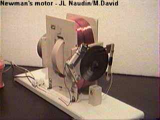
The Newman's Energy Machine
By JL Naudin/M.David
created on 06/12/98 - JLN Labs - last update on 06/22/98
06-22-98 - Additional comments from JL Naudin

In the two diagrams above you can see :
The first diagram shows three curves :
1-a) The BLUE
curve (the input
current) is the real current flow
INPUT measured accross a 100 ohms resistor connected in series
with the coil. This current input is measured while the
rotor is rotating in the coil.
1-b) The RED
curve (the "inductor
charging" current) is the
current needed for FILLING the COIL with magnetic energy while
the voltage is maintained constant. The magnetic energy in the
coil is Wm=0.5*L2
after 5*Tau = 5*L/R about 68 ms. This is the Magnetic energy
charging current when the rotor does not
rotate in the coil.
1-c) The GREEN
curve (the "magnetomotive"
current) is the current GENERATED by
the rotation of the magnet through the coil. You may notice that
the shape of the curve has the SAME shape than the voltage
generated in the coil shown in the "free run" diagram.
This confirms the fact that this current is the real
"magnetomotive" current.

Link to the Efficiency testing - Test RUN 1
If you need more informations or if you have any suggestions send me your Feedback
![]() Email
: JNaudin509@aol.com
Email
: JNaudin509@aol.com
Return to the Newman's Machine Main page